When I first uninstalled the instrument cluster in my car a combination of inexperience, carelessness, and difficultly seeing behind the cluster resulted in me not really paying attention to which wire went where. When it came to putting it back in I was at a bit of a loss. After some question asking in forums and YouTube video watching I was able to figure it out. I thought I’d show what I did here to perhaps help others in my situation.
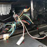
First, here are the wires we’re working with
Because my car has an AW70 automatic transmission there will be a couple of unused wires that should be pushed out of the way before installation.
What Are We Looking At Here?
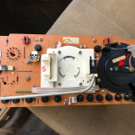
This is the back of my cluster which includes an electronic speedometer and a clock rather than a tachometer.
Two things to note here. First, when I first removed the cluster I was pretty much pulling out anything that seemed to be connected to anything. This included the semi-transparent connector on the back of the clock to the right in this photo. I have added an arrow to indicate that this should be plugged into the spade terminal. Second, the thing hidden by the skull and bones is not a connector you should worry about. It was used during manufacture to calibrate the speedometer, and if you do anything to you will destroy the instrument. As you can see here, Volvo began wrapping it in foam at some point to ward against accidentally connecting it. Be aware and don’t touch it either, dear reader.
The rest is self explanatory. The round and half moon connectors (1 and 2) only fit in one place. 5 slots onto the edge connector on the back of the speedometer. 6 is power for the overdrive indicator.
I hope this helps.

