So I decided that in preparation for inspection I should replace the front shocks. I had already replaced the rear ones a year ago. That was quite easy, but I knew the front would be more challenging and include things like spring compression and other sort of scary procedures. I foresaw the following set of actions I’d have to do before getting a place where I could remove the old shocks:
- Up top, remove plastic cover that hides the 24mm nut that holds the shock absorber as well as the three nuts that hold the strut assembly to the body.
- Remove the tire
- Disconnect the brake line from the brake caliper and then remove the caliper from the steering knuckle
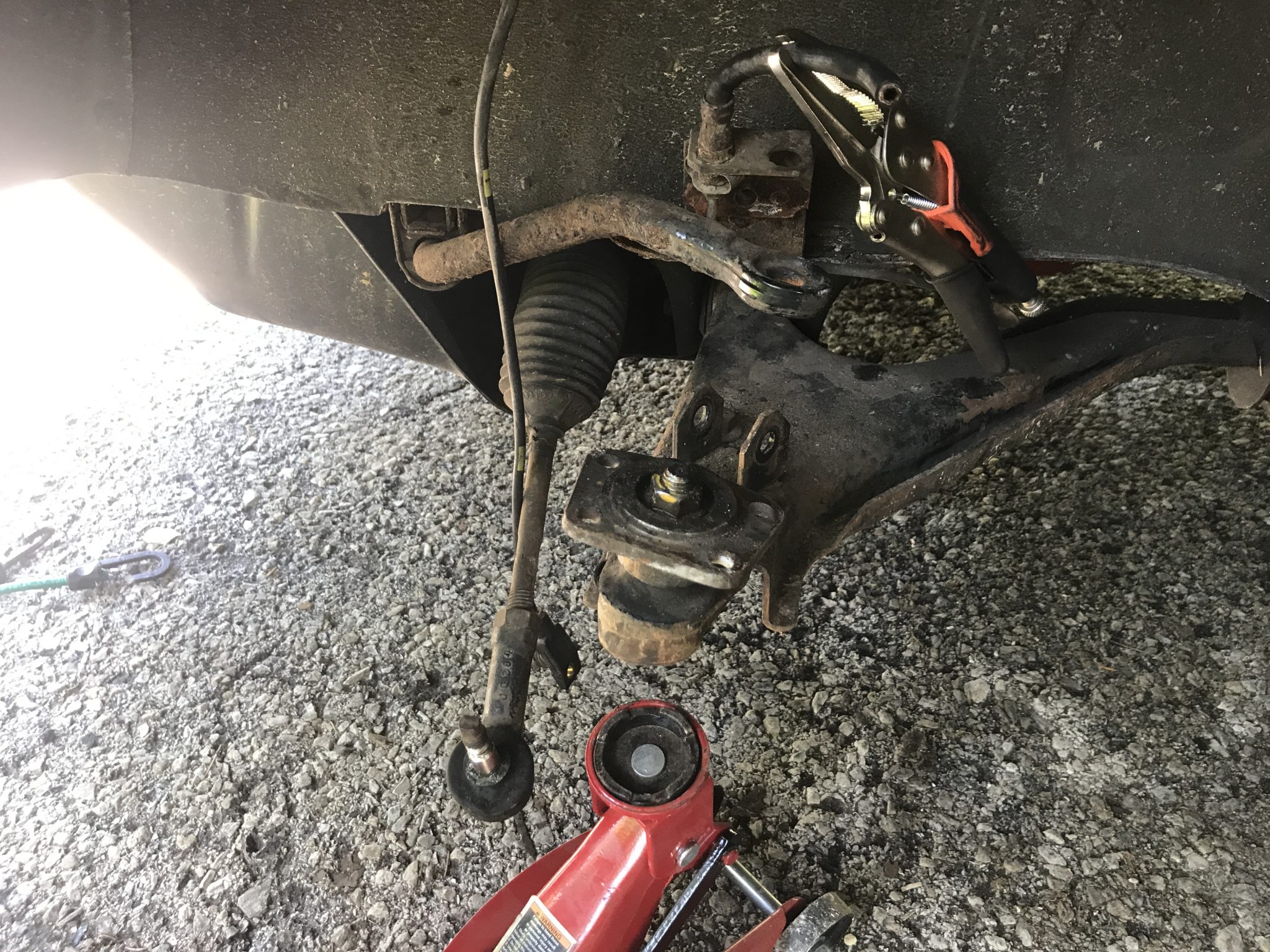
- Unbolt the steering end link from the steering knuckle and the sway bar end link from the sway bar. This will allow the lower control arm to move down far enough to get the strut out.
- Remove the four bolts that connect the strut to the ball joint and remove the strut from the car
At that point I could work on compressing the springs and removing the old shocks. Of course, things did not go according to plan. I followed the above list with little issue but as soon as the strut was out of the way I saw that a bunch of other components were in not great situation. Specifically:
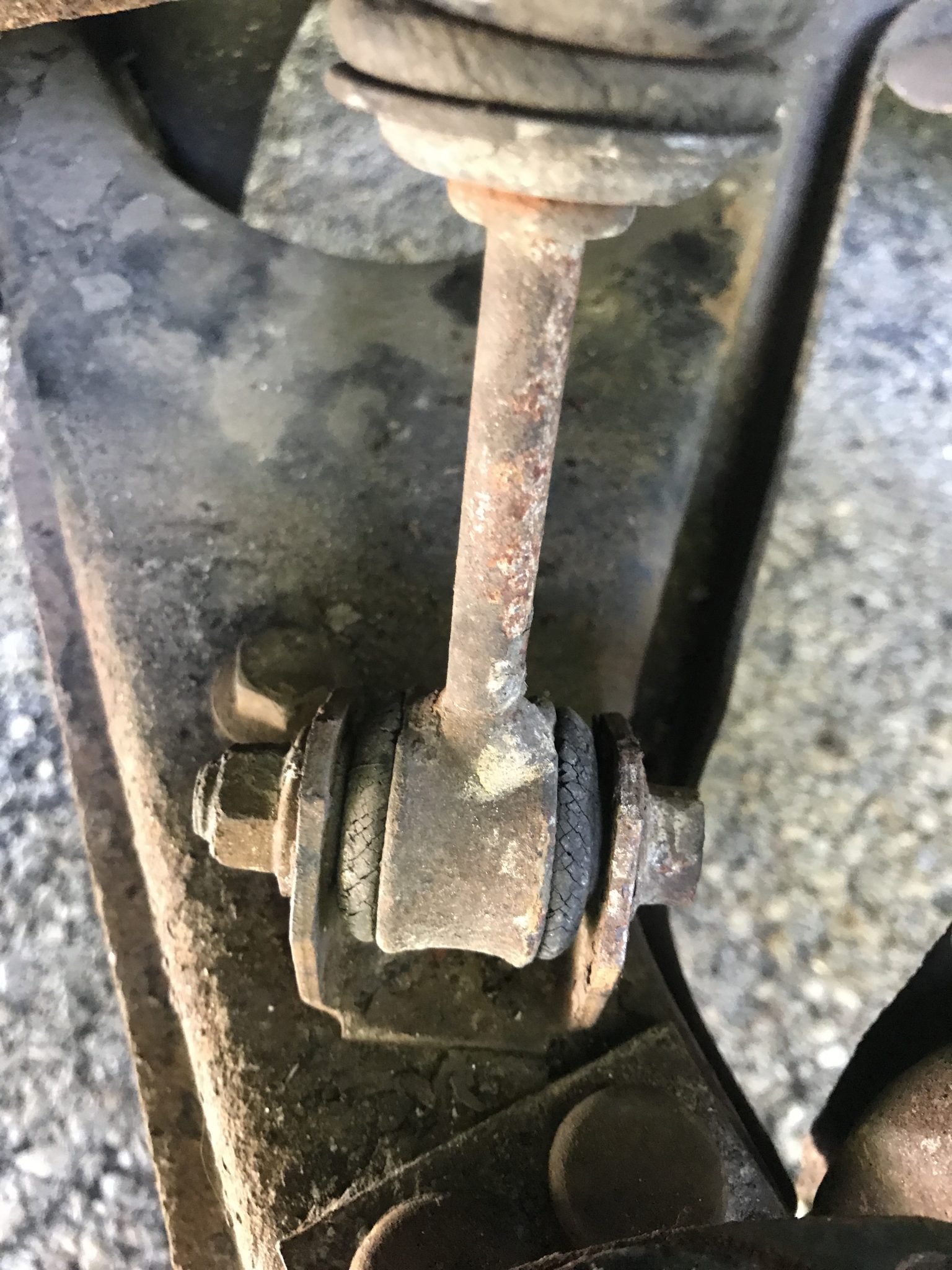
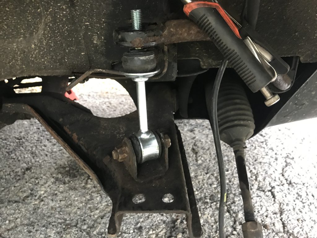
- The sway bar links on both sides were either very rusty, had rubber bushings that were falling apart, were bent, or some combination of those.
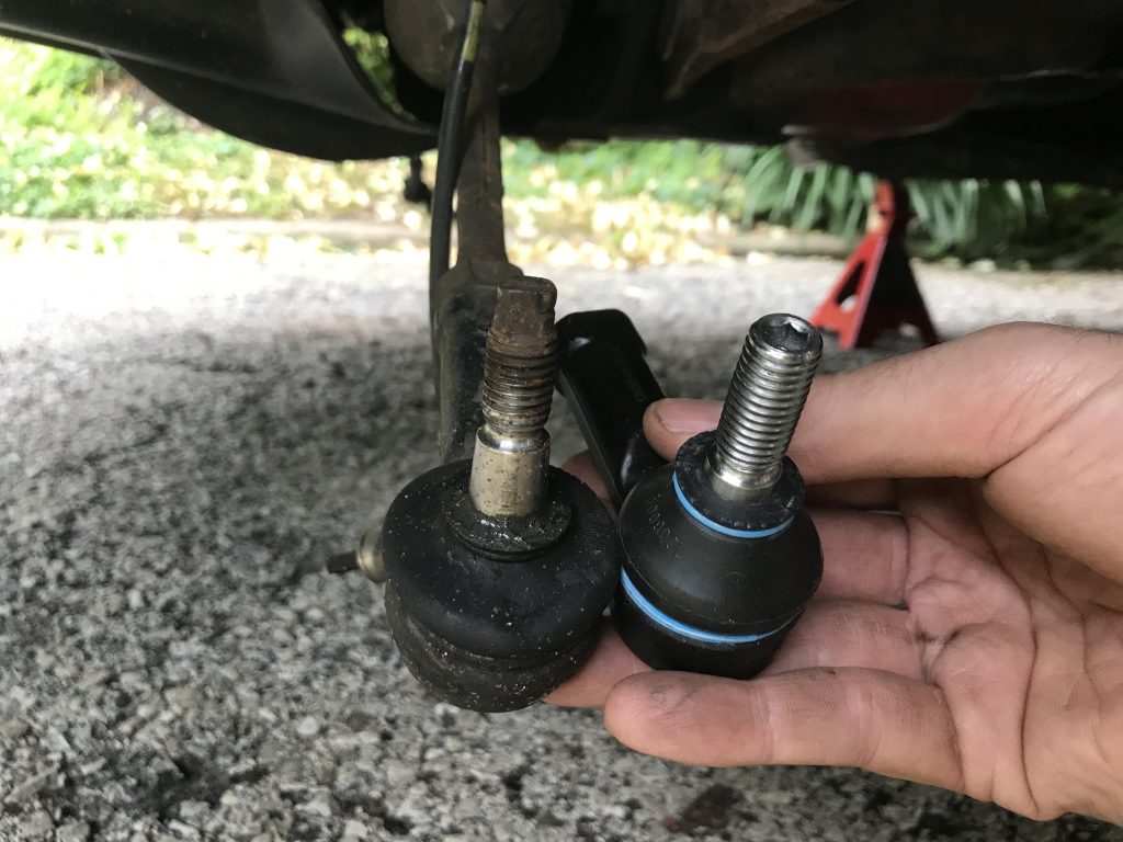
- The rubber parts of the tie rod ends were visibly worn out.
- The rubber brake line hoses were fairly well abraded.
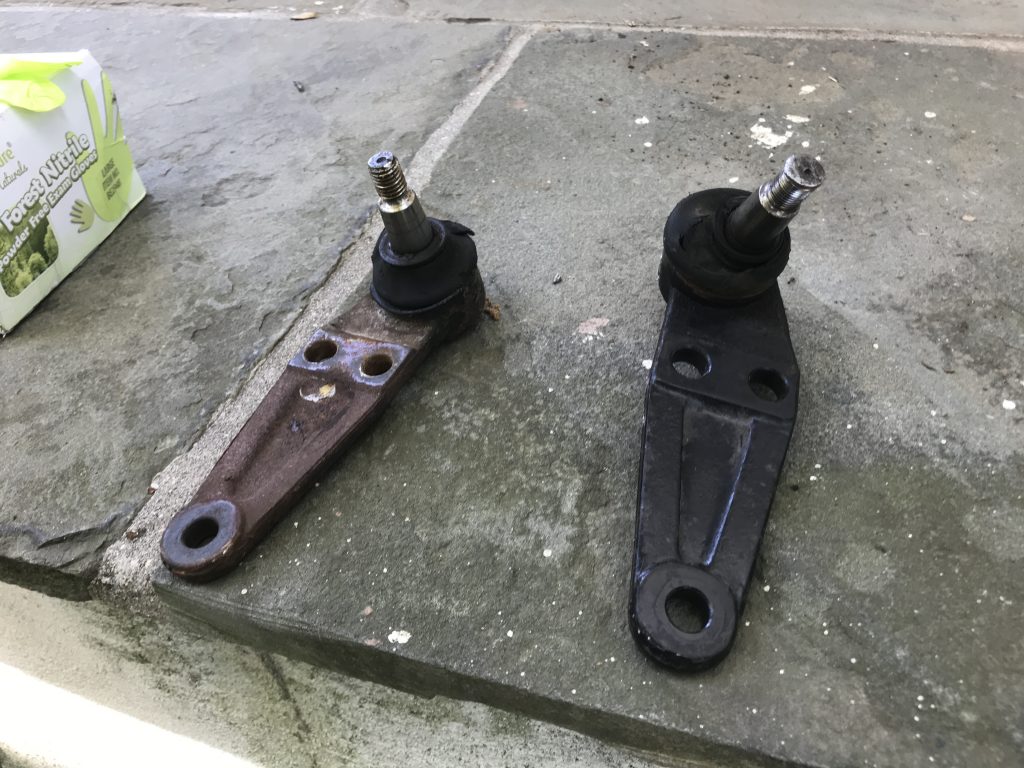
- The rubber dust covers on the ball joints were starting to or had separated.
This was all suboptimal, so since I had the struts out I figured I’d replace these things too. Of course the bolts on everything were crusty and hard to get loose, especially the ones on the hard brake lines. A bunch of Kroil took care of that (eventually).

Replacing the Suspension Parts
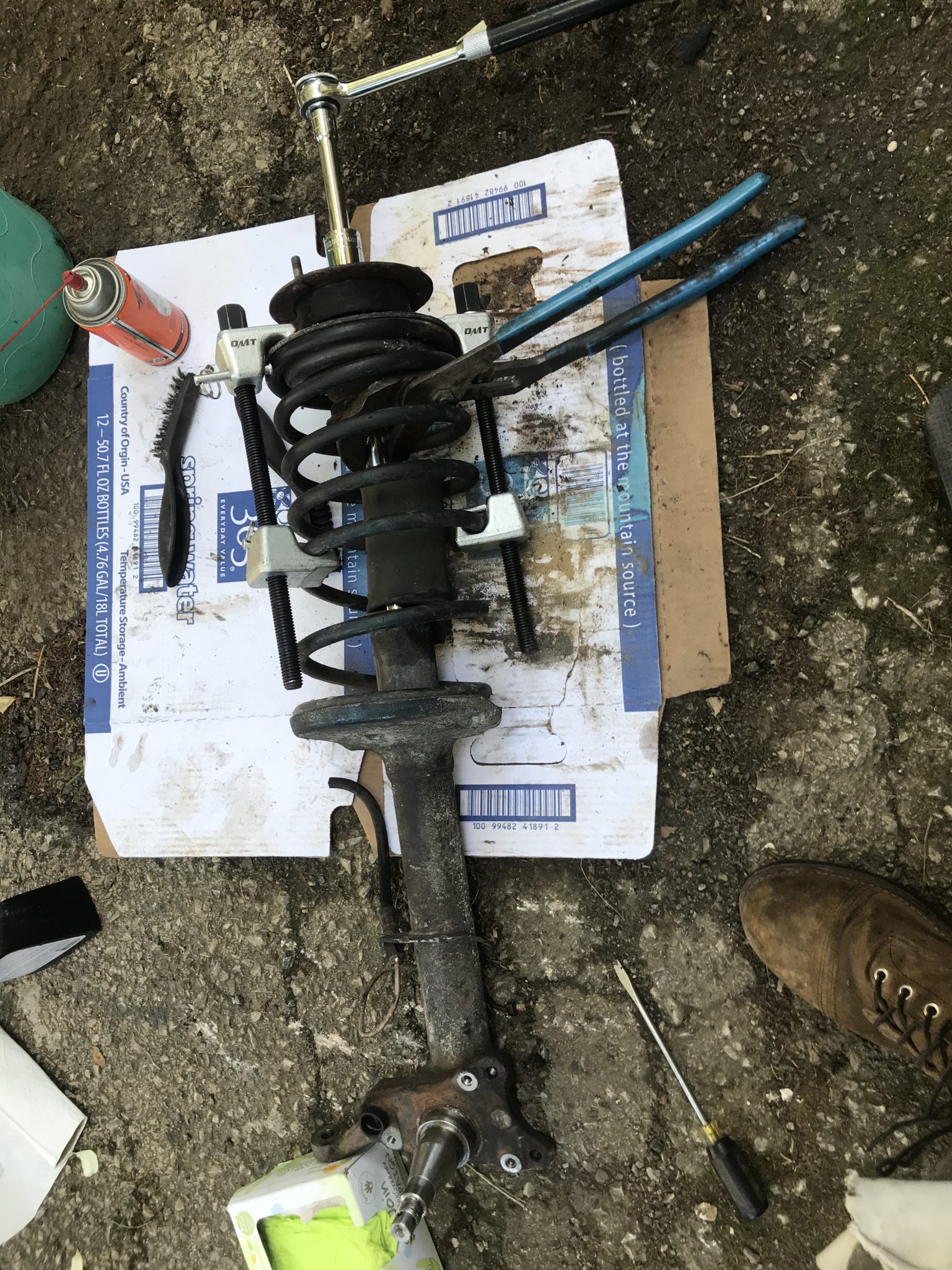
Once the strut was out the main task was getting the locking nut off the top of the shock absorber piston. This was pretty well stuck on, and since the piston will rotate within the stock along with the nut you have to find a way to keep it still while you crank on the nut. Volvo’s way of doing this is to use a a pass through 24mm socket and wrench while holding the piston in place from the top. I did not have a pass through socket wrench so what I ended up doing was using a big set of channel locks to grasp the piston about halfway down its length and standing on it to keep it from rotating while I worked the nut at the top with a deep 24mm socket and a ratchet with a cheater bar. This eventually worked for one but not the other. For that one I borrowed a heavy duty impact gun which loosened the nut enough that I could start working it off. All told it was a giant pain, and all these janky techniques were made extra terrifying by the fact that those springs were under compression the whole time. In hindsight what I should have done was loosen the nuts a little while they struts will still on the car either using the impact gun or, as I discovered later, a 1″ box wrench inserted at an angle with an adjustable wrench holding the piston steady. Hindsight is 20/20, as they say.
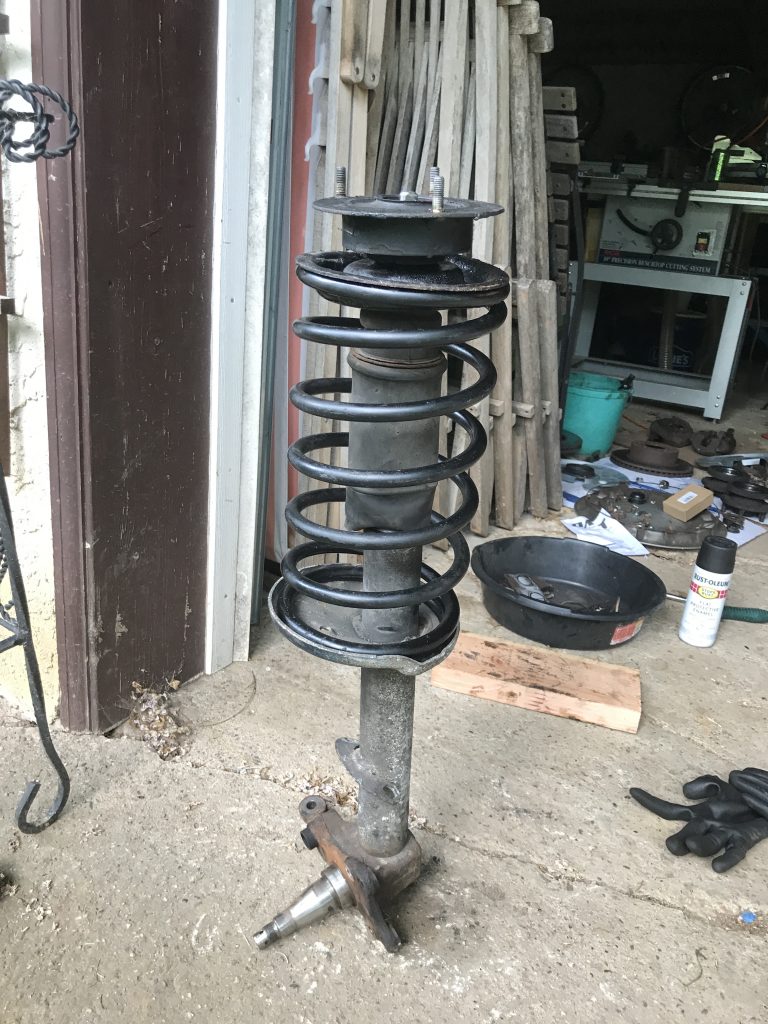
Once the shocks were out and the springs uncompressed replacing the shocks was easy. I took the opportunity to paint the springs, which had some rust starting mostly at the top and bottom where water could pool inside the end plates, to guard against future corrosion. It also made them look nice. A note to others doing this operation: make sure the retaining nut that keeps the shock cylinder from moving it tightened as tight as possible. The first time I took the car out after replacing the shocks I was getting a terrible THUNK THUNK when going over even small bumps. This was because the nut had come loose slightly which allowed the shock to move up and down about a quarter of an inch. It’s much easier to tighten up while the strut is off the car, so make sure you do it right the first time.
While I was addressing the struts my other front end parts came in. These included new ball joints, new sway bar end links, new tie rod ends, and new rubber brake lines. In they went. For reference, these are the torque specs for the various bolts involved.
- Ball Joint to Control Arm: 115Nm/85 ft-lb
- Ball Joint to Strut Anchor: 60Nm/44 ft-lb
- 4 M8x30 bolts from Strut Anchor to Strut Tube: 23Nm/17 ft-lb
- Sway Bar Link to Control Arm: 60±10Nm/44±7 ft-lb
- Sway Bar Link to Sway Bar: squish the bushing down to 42mm
Everything just bolts on. Remember to mark the position of the old tie rod ends so you don’t mess up the wheel alignment. I did this but later got a needed realignment done by a professional while I was getting my yearly inspection done. More on that later.
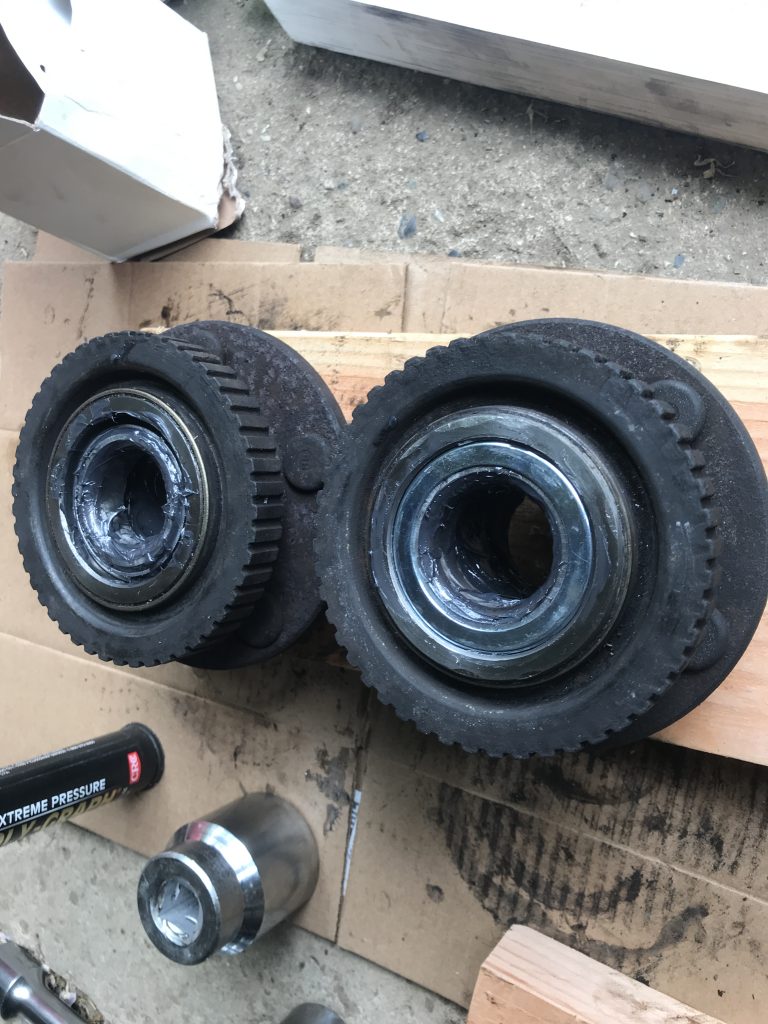
New Wheel Bearings
Next up were the wheel bearings themselves. Each hub had two conical bearings, one on the outside edge and one on the inside. I got the old ones out using a hammer and a set of brass punches and the new ones in by placing conveniently sized sockets against the outer ring and hitting it with a hammer. Obviously this isn’t the best/right way to do it, but the right way takes a hydraulic arbor press, which I don’t own, so sockets and hammers it was. After that I packed the bearings with grease and put the dust covers on.
The hubs should slide right onto the spindles with no force necessary. The key to this, though, is lining the hubs up just right on the spindle. I had to try it a number of times before I centered the hubs correctly when putting them. If they aren’t centered the tolerance are tight enough that the hub will get hung up on the spindle. Properly centered they’ll slide on smooth as silk. Once I got the hubs on I packed the inside of the bearing with a lot of grease and screwed on the castle nuts. I wanted to make sure the bearings were well seated, so I tightened the nuts all the way down and gave them a bit of oomph to make sure everything was pressed in as well as it could be. Then I backed the nut off until the hub spun without drag and secured it with a new cotter pin. Then I smeared a bunch more grease on the inside of the dust cover and put those on.
New Dust Covers and Brake Lines
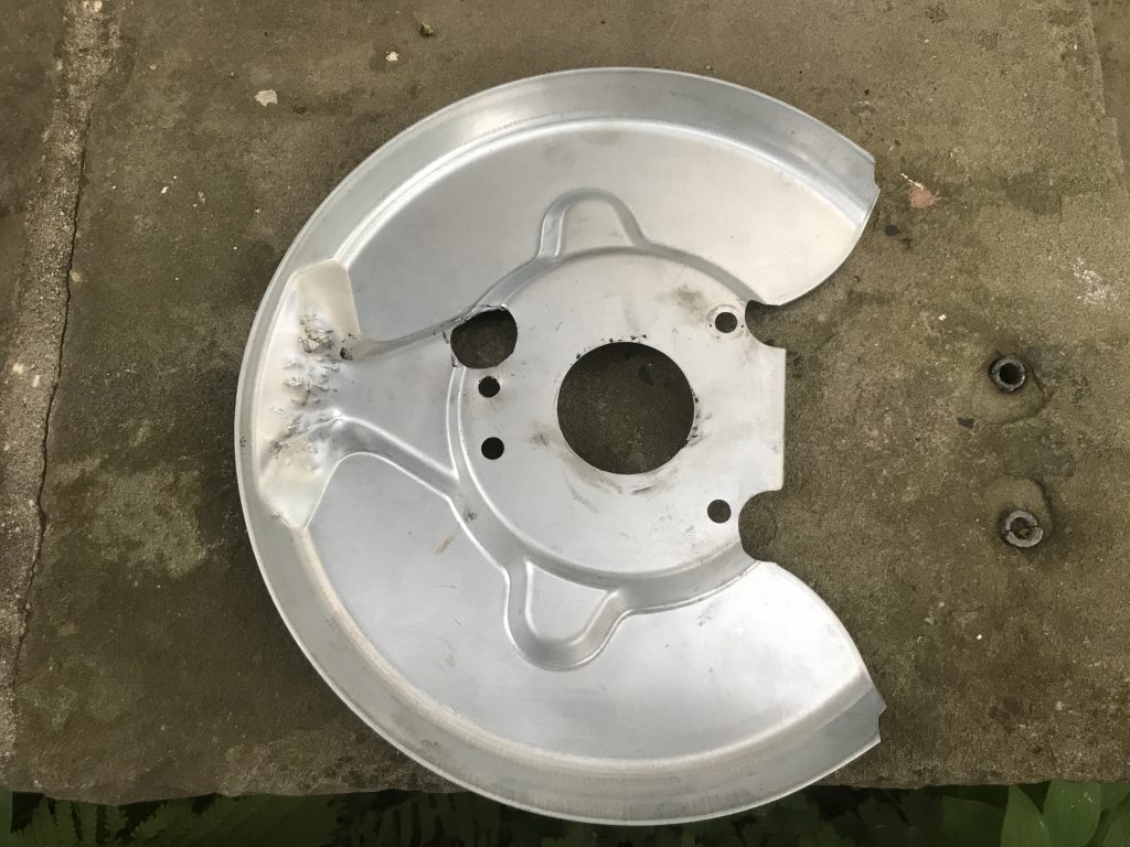
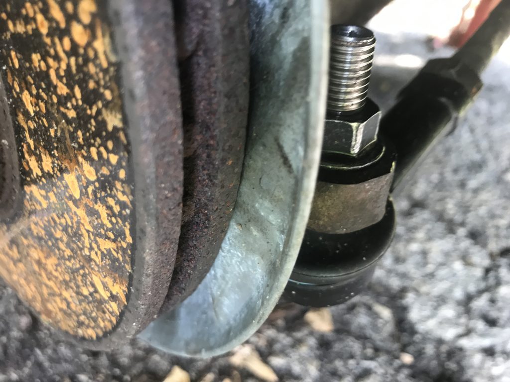
Awhile ago I had ordered some new brake dust covers to replace the ones in the front that had completely disintegrated. These are somewhat hard to come by, especially for cars with an ABS system. What I ordered probably wasn’t 100% the correct part as was evidenced by the fact that the bolt holes only sort of matched up and the embossed part meant to avoid the tie rod end wasn’t quite the right shape. This plate also was missing the hole where the ABS sensor passes through, but I knew this already. Ultimately I ended up shaping the edge of the plate a little to clear the tie rod end and cut a hole for the sensor.
Once those were on I reattached the brake calipers and hooked up the new brake lines. After having opened the lines up the system needed bleeding which was extra good for me because the brake fluid in the car was very old and very dirty. Instead of the near translucent color of new fluid the existing fluid was reddish brown. The bleed pulled a lot of that out, but I should probably completely flush and replace the fluid in the near future for good measure. I also considered replacing the brake discs as they had some scoring on them, but it wasn’t a lot and the thickness of both was well above the minimum of 12.7mm/.5 inches.
Results
I must admit that I did all this work several months ago and have just not had time to finish writing all this down. The upside of that is that I can report that the car has been running fantastically. The ride is much smoother. However I did end up having to do one more semi-major job on the car before I could pass inspection. Hopefully now that this entry is done I’ll be motivated to write about that.