After I got the air intake system back together I spent a little time pondering a few spots in the vacuum system that didn’t seem to have any connections. My library of photos was no help, and I kicked myself for not documenting all this stuff more thoroughly. Finally I got a flashlight and peered down into the innards of the engine bay and noticed a stray hose coming from the brake booster that had no place to go. Where it seemed like it should go was currently occupied by the other side of the IAC. Then it hit me: I had the IAC going to the completely incorrect place. Where the IAC was going on the side of the throttle was where the brake booster’s vacuum line was supposed to go and the open spot on the back of the intake was where the IAC was meant to connect to! I switched them around and am now confident that everything is in the right place. To help others I drew up a simple (read: crude) diagram of where the various vacuum hoses should go.
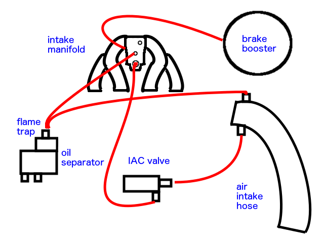
Not pictured here are the two lines from the charcoal canister that attach to the throttle body and a line that goes through the firewall to what I think is part of the air conditioner system.
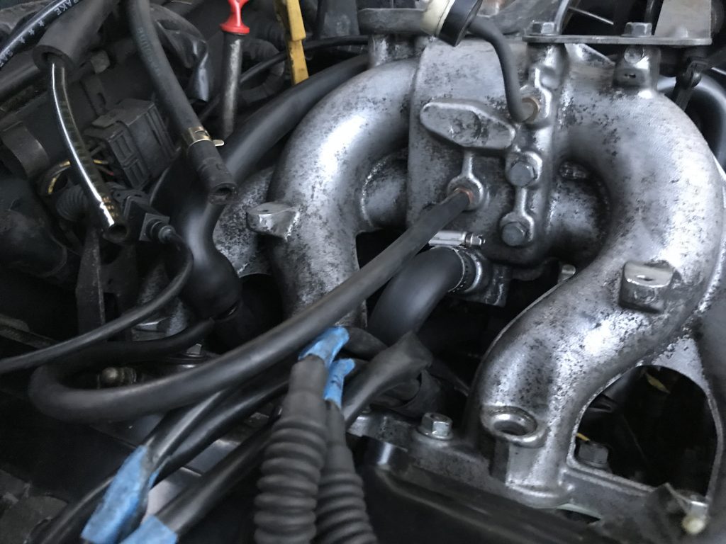
Back of the intake 
Front of the intake and the throttle 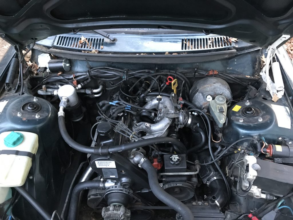
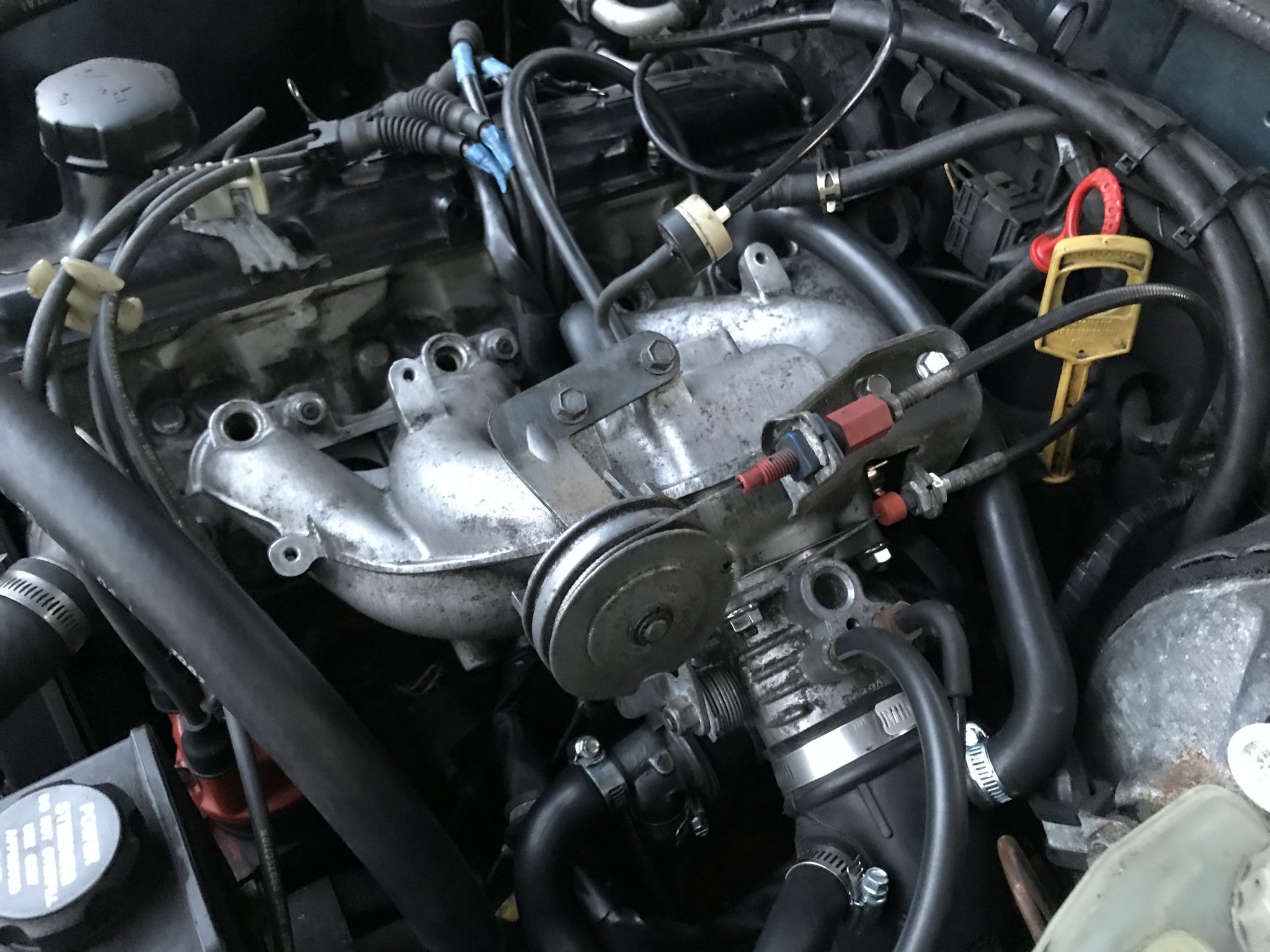
The whole shebang
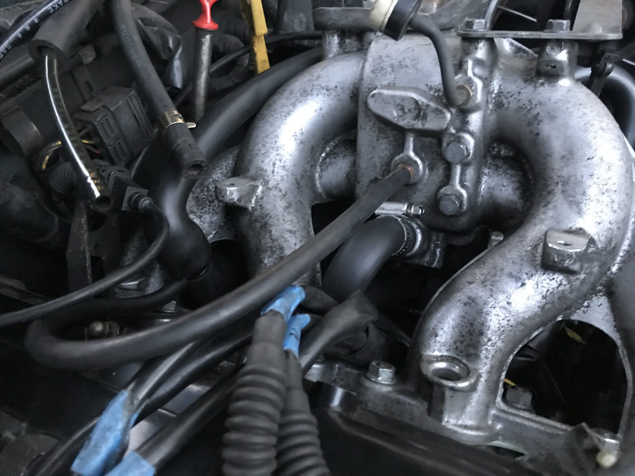

Note that I have the check valve on the aforementioned climate system vacuum line backwards. It should be “white towards the intake manifold.”
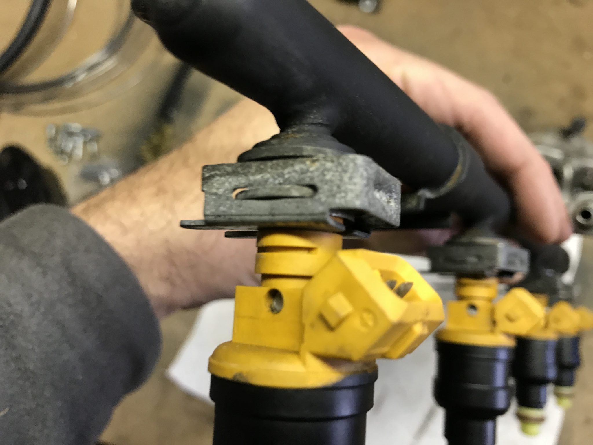
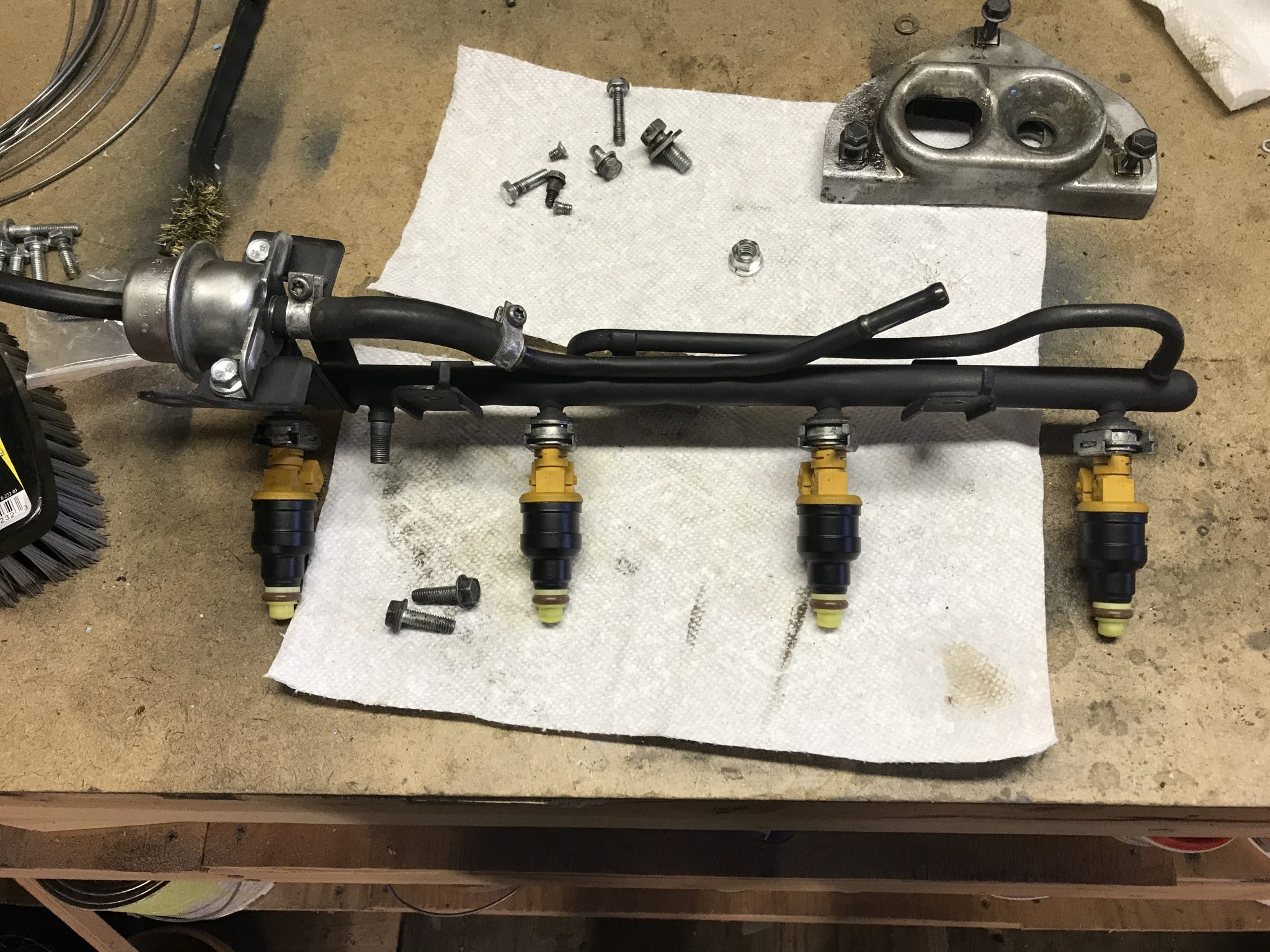
The Fuel Rail
The next step will be to reattach the fuel rail at which point the engine will be ready to try out. I reinserted the injectors and attached the new fuel pressure regulator. I did this slowly and evenly, tightening the bolts that secure it to the rail so the o-ring that seals its connection properly.