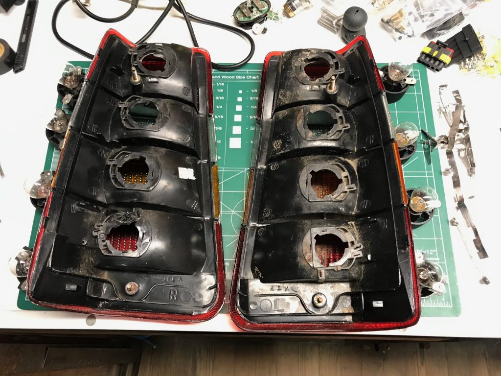
You may remember that I had bought a new set of tail lights from someone one the internet. I actually tried installing them pretty soon afterwards but found that even though I knew all the bulbs to be good, once the lights were in the car they intermittently stopped working. Electrically, Volvo 240 tail lights can be a bit problematic. They make heavy use of spade connectors and the ground connections are done along a bus bar of thin metal, all of which are prone to corrosion. On top of that the plastic of the assembly and the sockets in which the bulbs sit can warp over time and disrupt contact between the tabs and the connectors. The solution to this has been to remove all that stuff and solder the connectors together, and this is what I decided to do.
Preparation
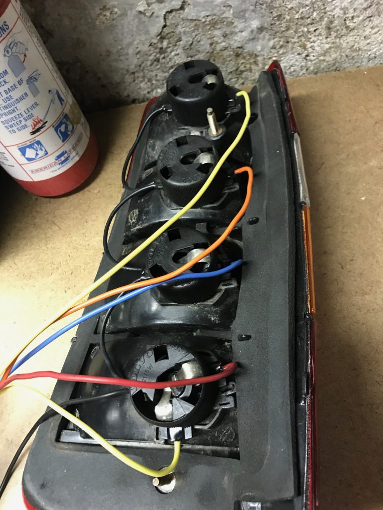
I started by prising out the various connecting tabs (seen to the right in the above photo). These are simply wedged into the plastic housing by small tabs. Putting the housings aside, I began to solder the ground tabs of the bulb sockets together. The ground tabs can be identified by tracing them into the socket and finding the one that contacts the side of the bulb cap rather than the terminal(s) at its bottom. The length of wires I used for the grounds resulted in loops which made attaching the sockets easier but eventually complicated the fitment of the lights to the car. I would recommend a shorter length and a less pronounced bow.
Soldering
Next I measured out different colored lengths of wire for the positive terminals and soldered them on. I used 16 gauge wire, but 18 will also do. Make sure to use stranded wire rather than solid as you’ll need some flex, and flatten and spread the stranded at the connection point to allow them to wick the solder a bit for better a connection. My general soldering technique was to heat a small blob of solder and drop it on the socket tab. Then I’d apply heat to the tab itself until that blob melted. This was a sign that the tab itself was hot enough to accept solder directly. Hold the wire to the tab and heat it until solder melts into the splayed out ends and runs into the solder you had already applied to the tab. A “helping hand” device is particularly handy to do this (no pun intended).
A note on soldering wires to tabs with a relative large surface area like the bulb socket has. Any heat you dump into that tab will quickly be spread throughout the entire structure, so to get enough heat localized on the spot where you want to actually solder requires a relatively high powered gun. I have a crappy reflow station I bought cheap from a RadioShack when that company was going out of business, but it can get up to around 800° F which worked well enough to accomplish this task. I’m not sure your average 30W soldering pencil could do it.
Finally, put a small length of heat shrink tube, enough to cover the end of the tab and the solder and hit it with some heat. This will help prevent corrosion and protect the join. Keep in mind that for the ground connections you’ll have to put two wires through three of the four connections, so plan ahead.
Improving the interface
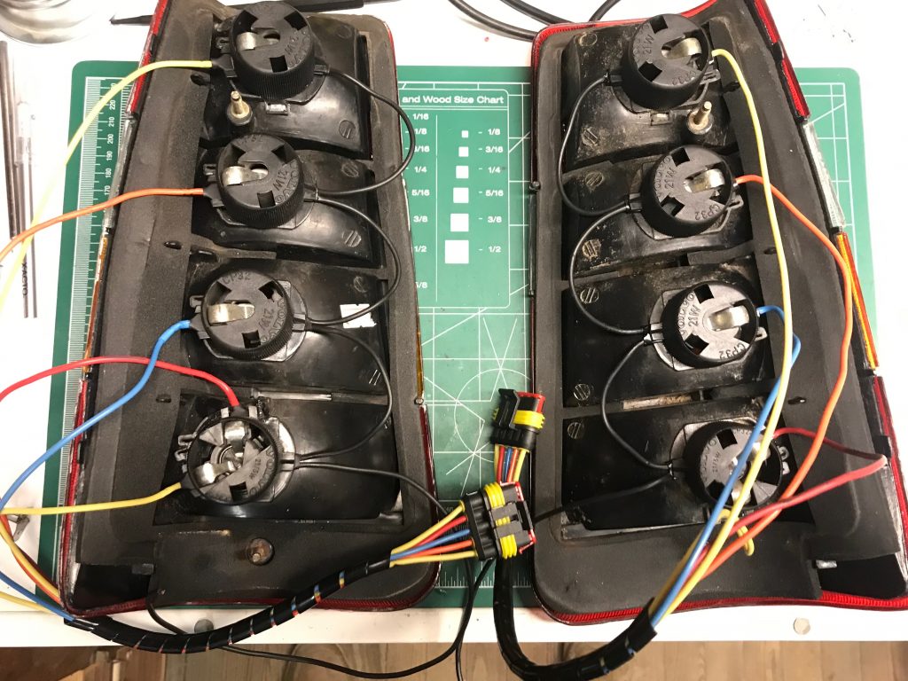
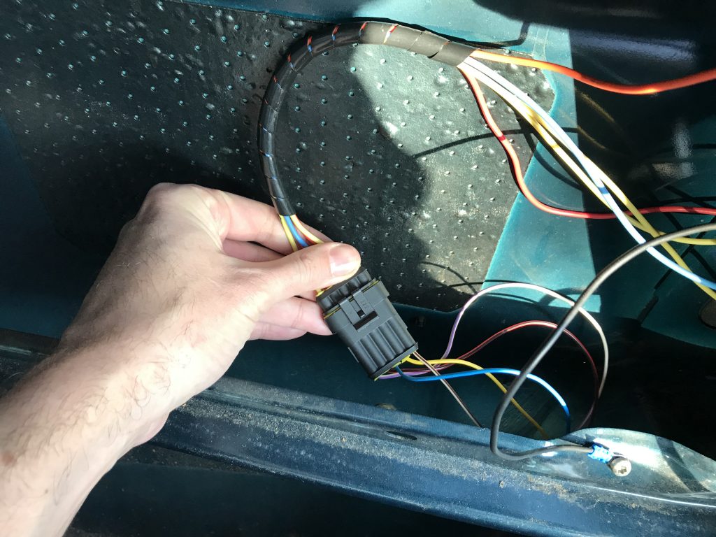
Once all the connections were made and covered with heat shrink I attached the other end of each to the female crimp terminals of a 5 pin connector I got from Amazon. Once these were all in place I snipped off the original spade connectors on the wiring in the car, crimped the male connectors onto the end, and, taking care to put the wires in the order corresponding to the way I ordered the wires on the lights’ sides, inserted them into the other half of the connector pair.
My hope here is that soldering these connections, covering them, and using the waterproof connectors will serve to make the lights more reliable and easier to work on in the future if need be.
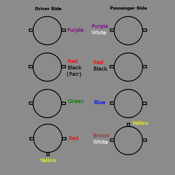
Because reading wiring diagrams out of my Bentley service manual stinks, I’ve included my own much clearer diagram. All the unlabeled tabs are black ground wires.